
***How-To*** Install Valve Springs & Valve Stem Seals

Thread Starter
Time to become a Premier Member!
Joined: Aug 2003
Posts: 4,816
From: Whitby
Tools Required:
-3/8 Ratchet
-1/2 Ratchet
-10mm socket
-12mm deep socket
-14mm socket
-19mm socket
-5/8 spark plug socket
-6� Extension
-Breaker Bar
-Socket handle to go into the 12mm socket
-Pliers or valve seal removing tool
-Valve spring compressor
-Hose from a leakdown tester
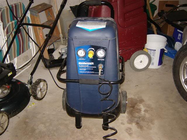
-Compressor
-Rubber mallet
-Telescopic magnet, if you drop the valve keepers
-Cam gear holder or 5mm punch (2) or 5mm allen key (2)
-Engine oil or assembly lube
We got to organize everything that�s going back into the head and identify what they are:
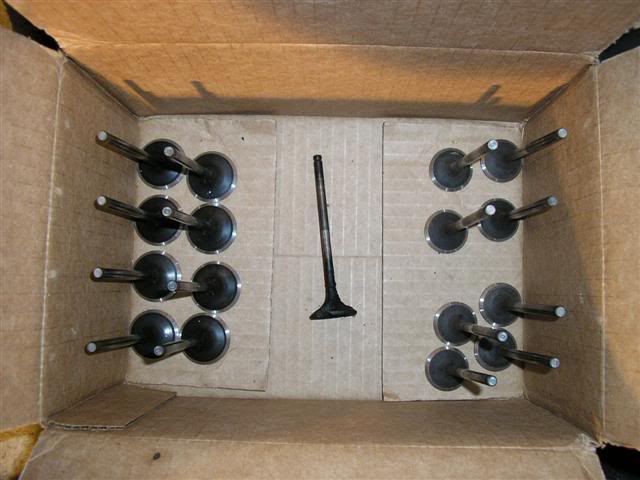
-valves
-valve spring seats
-valve stem seal
-intake valve spring(s)
-exhaust valve spring(s)
-retainer
-valve keepers
Valves (ignore my burnt exhaust valve in the middle)
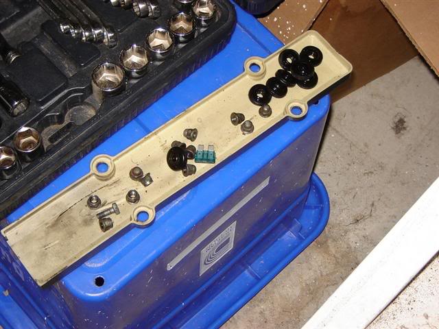
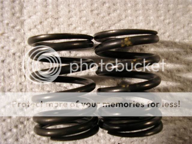
Valve springs, retainers, valve seats
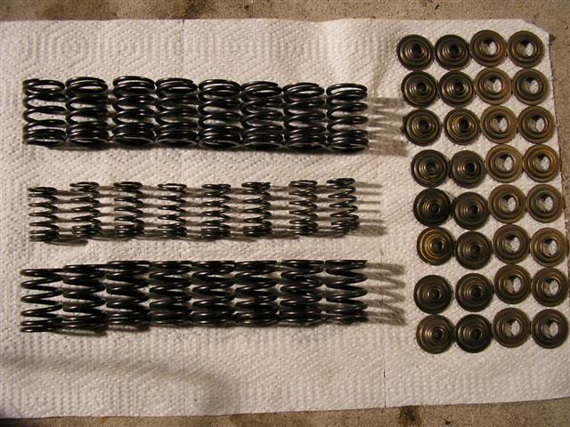
Top valve spring is the GSR outer intake, the middle is the GSR inner intake and the bottom is the GSR exhaust. The retainer is the 2 columns to the left with the small diameter hole used to hold the valve keepers. *Note* that in the picture the retainers are upside down. The valve seat is the two farthest columns to the right with the bigger diameter hole that goes over the valve guide in the head.
1) First things first, find a place to work on your car.
2) Then pop your hood and remove your spark plug cover(if applicable), spark plug wires and valve cover using the 10mm socket and ratchet.
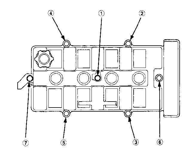
B18A/B Valve Cover
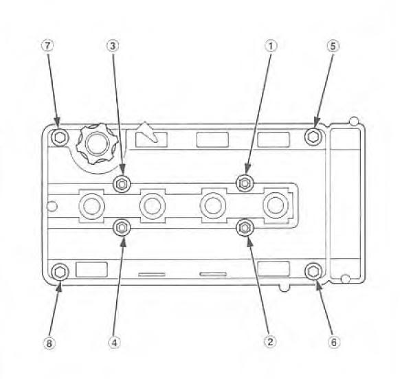
B18C1/5 Valve Cover
Valve cover removed
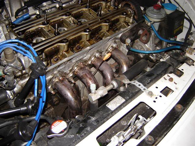
3) Then locate the under hood fuse box and take the cover off. **Optional Step**
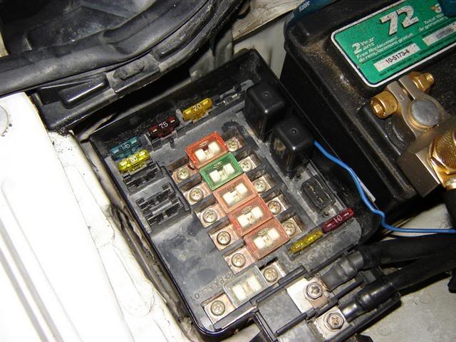
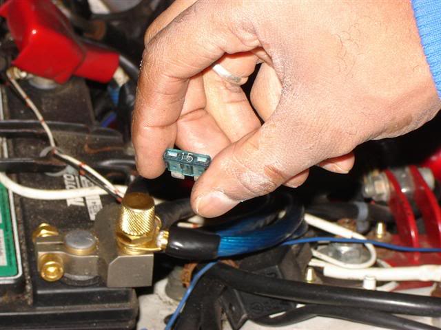
4) Then locate the 15amp fuse and remove it. This prevents fuel from being squirted into the engine when manually cranking it over to TDC for each cylinder. **Optional Step**
5) Place all the bolts and valve cover grommets in a safe place. For me it's in the spark plug cover.
6) Now start to remove each spark plug using the 5/8� spark plug socket extension and ratchet, like so. I started at cylinder 4
7) Now that the spark plugs are removed, grab your 19mm socket and proceed to turn the crank to TDC for cylinder 1
The crank pulley bolt is located here
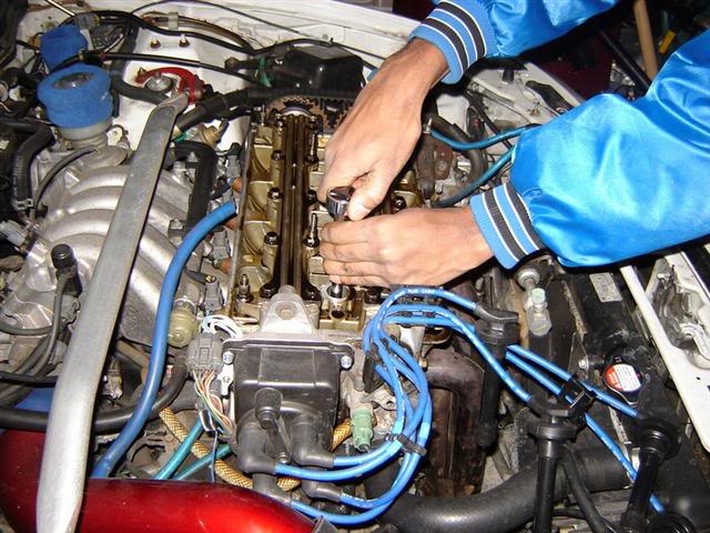
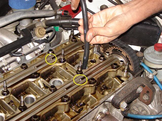
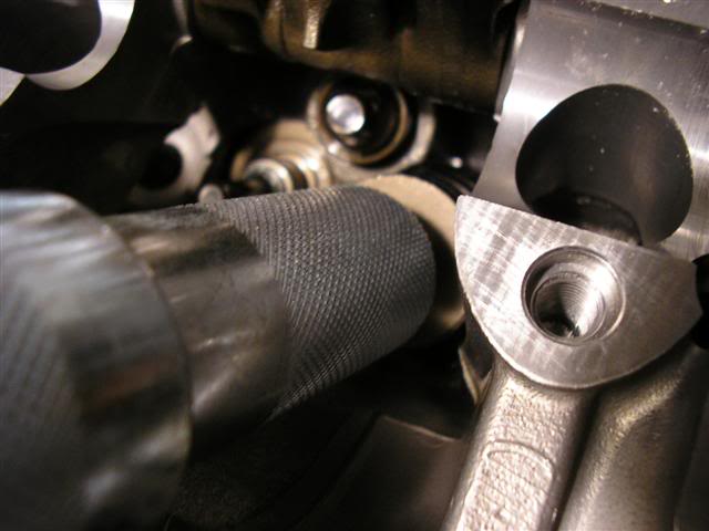
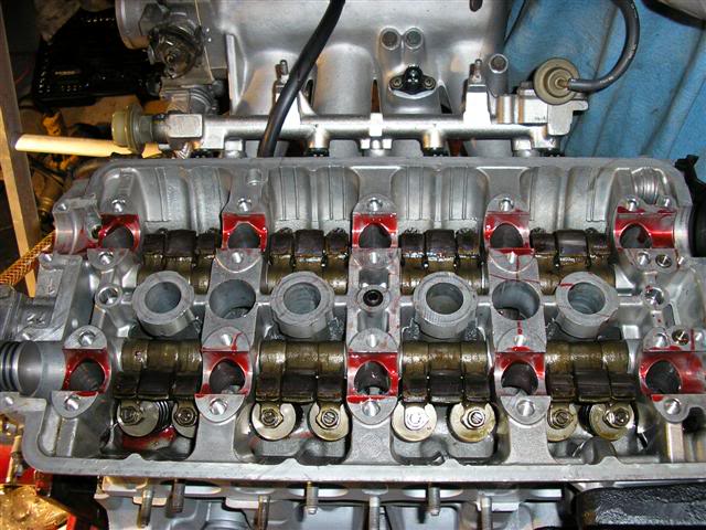
8) Loosen NOT remove both cam gear bolts with your 14mm and breaker bar. Do Not use an impact on these bolts. To make it easy use the two 5mm punches through the cam plate holder and cam holder into the camshaft. Circled here in yellow.
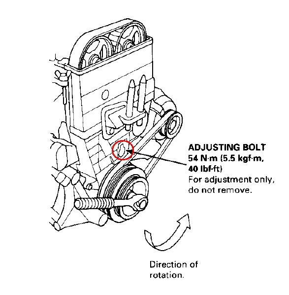
9) Loosen the timing belt tensioner bolt by removing the plug circled in red to expose the tensioner bolt.
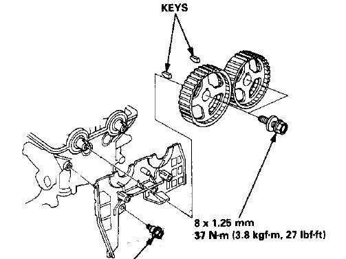
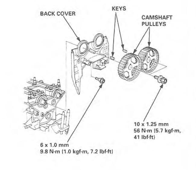
10) Remove the cam gear bolts along with the cam gears and key. Make sure to be careful when removing the cam gear & key to not drop or loose it.
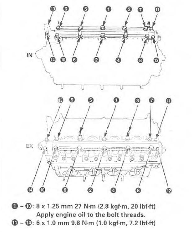
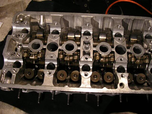
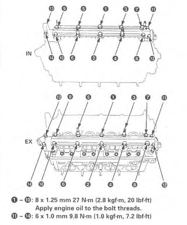
11) Remove both cam holder plates by loosening the 10mm bolts on the outside are first. Then the 12mm bolt starting from the outside bolts and working your way in. *The numbers on the picture below are for tightening*
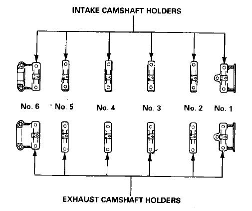
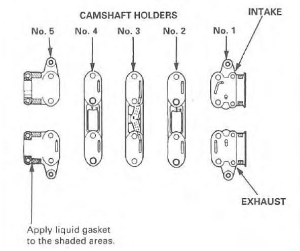
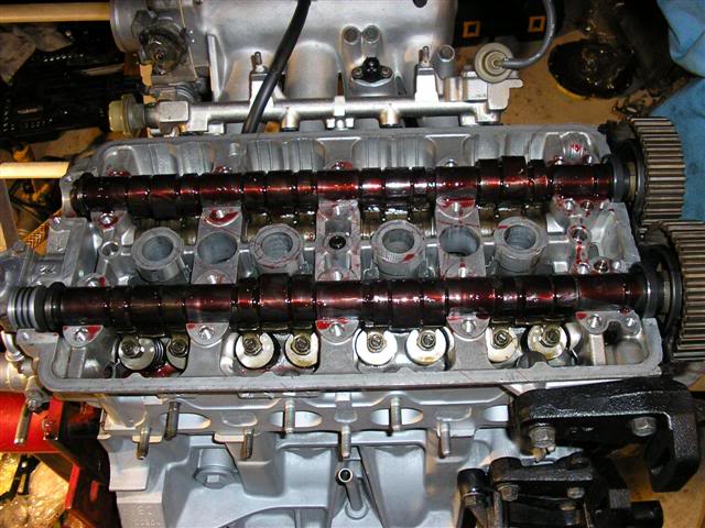
12) Remove the cam holders, taking care to remember how and where you removed them from
B18A/B
B18C1/5
13) Remove your camshafts and place them on a cloth in a safe place, along with the cam gears, key and cam gear bolt.
14) Grab your leakdown tester hose and screw the threaded end into the spark plug hole for cylinder 1. Plug the other end into your compressor. Make sure that the compressor is plugged in and turned on.
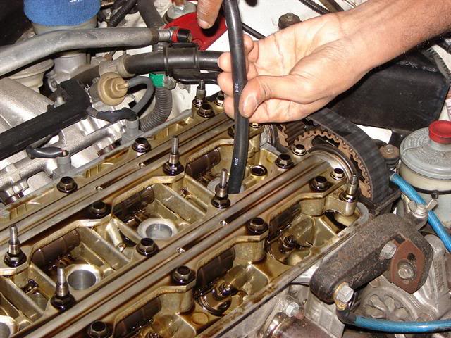
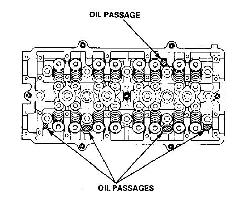
15) Very Important Step plug all the oil passages with paper towels. The oil passages are located here
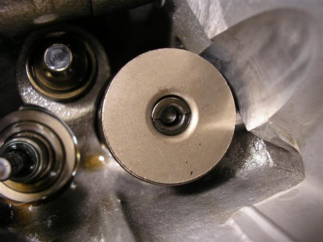
16) Grab your 12mm deep socket and extension then place it over the retainer
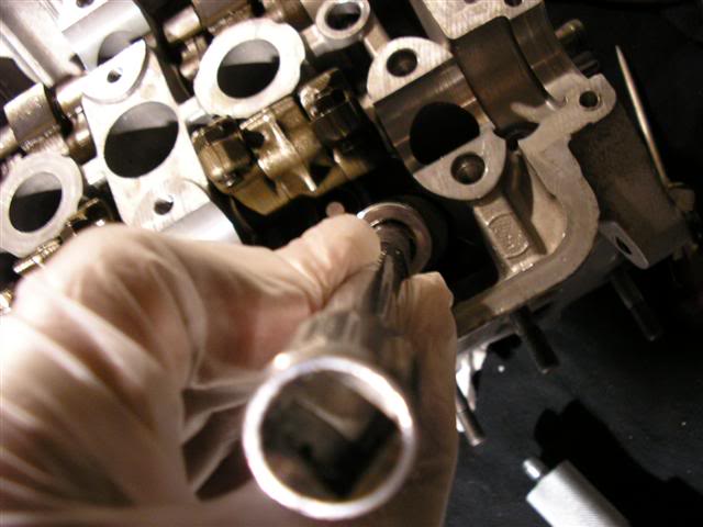
17) Give it a good wack with your rubber mallet to loosen the valve keepers from the retainer. Try not to loose the valve keepers
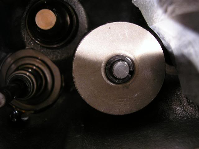
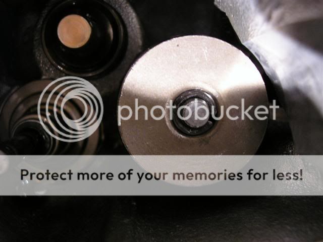
What the valve keepers installed looked like
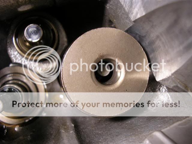
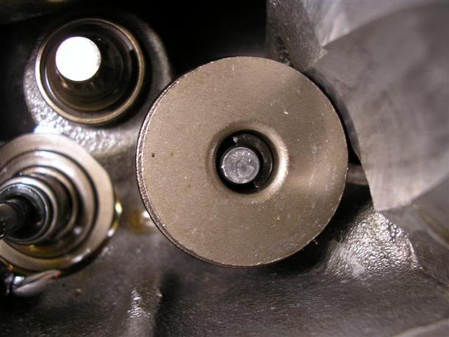
Valve keeper removed (how it should look after hitting it with the 12mm socket and rubber mallet)
18) Remove the retainer from the top of the valve spring(s)
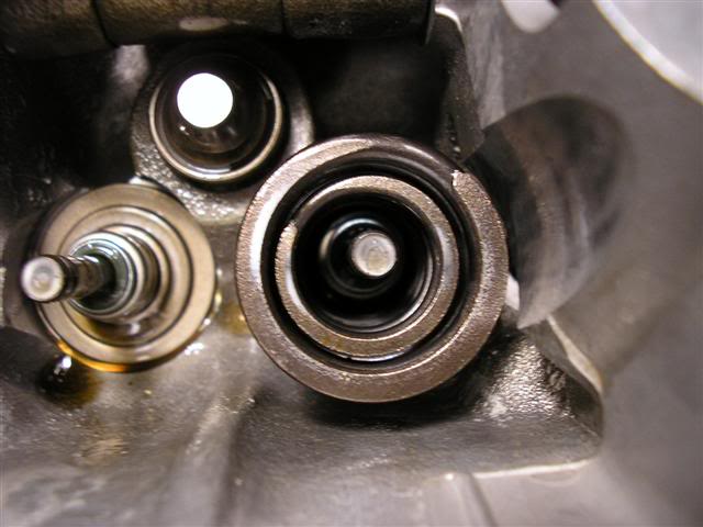
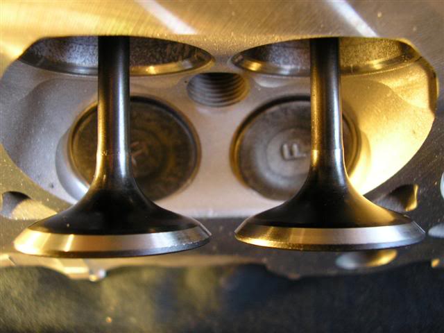
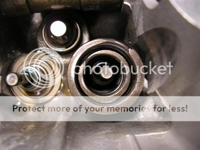
19) Remove the valve spring(s) to expose the valve seat and valve stem seal
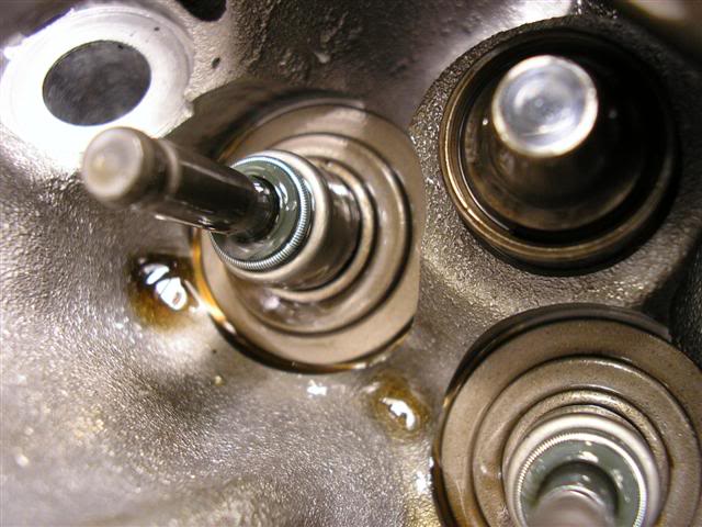
20) Grab your pliers or valve stem seal removal tool and remove the old valve stem seal. Left side has no valve stem seal, the right side does.
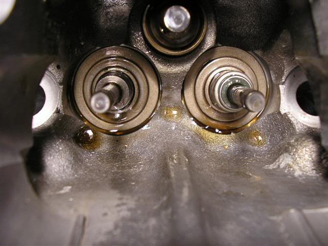
With all valves, valve springs, valve stem seals, retainers and keepers removed. *Note* head is off the car. If your doing this with the head on the car, do it one at a time.
21) Install the valve seat buy just placing it over the valve guide. Those that are doing this while the head is still in the car skip this step.
How it looks with no valve seat
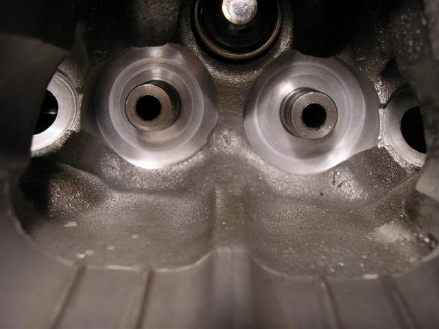
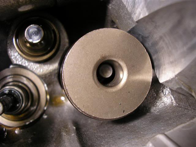
How it looks with the valve seat installed (left side)
22) Now lube the valve stem with oil or assembly lube and place it into the valve guide. Those that are doing this while the head is still in the car skip this step.
-3/8 Ratchet
-1/2 Ratchet
-10mm socket
-12mm deep socket
-14mm socket
-19mm socket
-5/8 spark plug socket
-6� Extension
-Breaker Bar
-Socket handle to go into the 12mm socket
-Pliers or valve seal removing tool
-Valve spring compressor
-Hose from a leakdown tester
-Compressor
-Rubber mallet
-Telescopic magnet, if you drop the valve keepers
-Cam gear holder or 5mm punch (2) or 5mm allen key (2)
-Engine oil or assembly lube
We got to organize everything that�s going back into the head and identify what they are:
-valves
-valve spring seats
-valve stem seal
-intake valve spring(s)
-exhaust valve spring(s)
-retainer
-valve keepers
Valves (ignore my burnt exhaust valve in the middle)
Valve springs, retainers, valve seats
Top valve spring is the GSR outer intake, the middle is the GSR inner intake and the bottom is the GSR exhaust. The retainer is the 2 columns to the left with the small diameter hole used to hold the valve keepers. *Note* that in the picture the retainers are upside down. The valve seat is the two farthest columns to the right with the bigger diameter hole that goes over the valve guide in the head.
1) First things first, find a place to work on your car.
2) Then pop your hood and remove your spark plug cover(if applicable), spark plug wires and valve cover using the 10mm socket and ratchet.
B18A/B Valve Cover
B18C1/5 Valve Cover
Valve cover removed
3) Then locate the under hood fuse box and take the cover off. **Optional Step**
4) Then locate the 15amp fuse and remove it. This prevents fuel from being squirted into the engine when manually cranking it over to TDC for each cylinder. **Optional Step**
5) Place all the bolts and valve cover grommets in a safe place. For me it's in the spark plug cover.
6) Now start to remove each spark plug using the 5/8� spark plug socket extension and ratchet, like so. I started at cylinder 4
7) Now that the spark plugs are removed, grab your 19mm socket and proceed to turn the crank to TDC for cylinder 1
The crank pulley bolt is located here
8) Loosen NOT remove both cam gear bolts with your 14mm and breaker bar. Do Not use an impact on these bolts. To make it easy use the two 5mm punches through the cam plate holder and cam holder into the camshaft. Circled here in yellow.
9) Loosen the timing belt tensioner bolt by removing the plug circled in red to expose the tensioner bolt.
10) Remove the cam gear bolts along with the cam gears and key. Make sure to be careful when removing the cam gear & key to not drop or loose it.
11) Remove both cam holder plates by loosening the 10mm bolts on the outside are first. Then the 12mm bolt starting from the outside bolts and working your way in. *The numbers on the picture below are for tightening*
12) Remove the cam holders, taking care to remember how and where you removed them from
B18A/B
B18C1/5
13) Remove your camshafts and place them on a cloth in a safe place, along with the cam gears, key and cam gear bolt.
14) Grab your leakdown tester hose and screw the threaded end into the spark plug hole for cylinder 1. Plug the other end into your compressor. Make sure that the compressor is plugged in and turned on.
15) Very Important Step plug all the oil passages with paper towels. The oil passages are located here
16) Grab your 12mm deep socket and extension then place it over the retainer
17) Give it a good wack with your rubber mallet to loosen the valve keepers from the retainer. Try not to loose the valve keepers
What the valve keepers installed looked like
Valve keeper removed (how it should look after hitting it with the 12mm socket and rubber mallet)
18) Remove the retainer from the top of the valve spring(s)
19) Remove the valve spring(s) to expose the valve seat and valve stem seal
20) Grab your pliers or valve stem seal removal tool and remove the old valve stem seal. Left side has no valve stem seal, the right side does.
With all valves, valve springs, valve stem seals, retainers and keepers removed. *Note* head is off the car. If your doing this with the head on the car, do it one at a time.
21) Install the valve seat buy just placing it over the valve guide. Those that are doing this while the head is still in the car skip this step.
How it looks with no valve seat
How it looks with the valve seat installed (left side)
22) Now lube the valve stem with oil or assembly lube and place it into the valve guide. Those that are doing this while the head is still in the car skip this step.
Thread Starter
Time to become a Premier Member!
Joined: Aug 2003
Posts: 4,816
From: Whitby
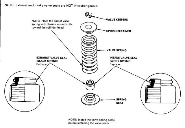
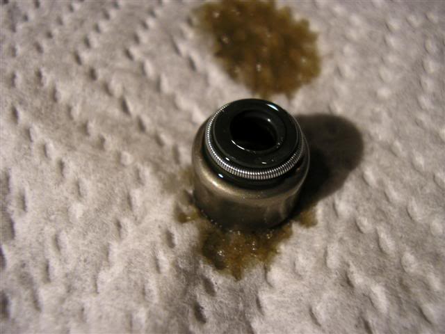
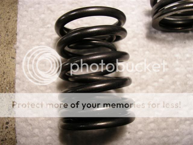
Next determine which valve stem seal it is that you’re going to install. A black spring around the valve stem seal means it goes on the exhaust side. A white or silver spring on the valve stem seal means that it goes on the intake side. They are not to be interchanged. The stem diameter on the intake side is bigger than the stem on the exhaust side and if you mix them up, your exhaust side will leak and your intake side will wear faster than normal.
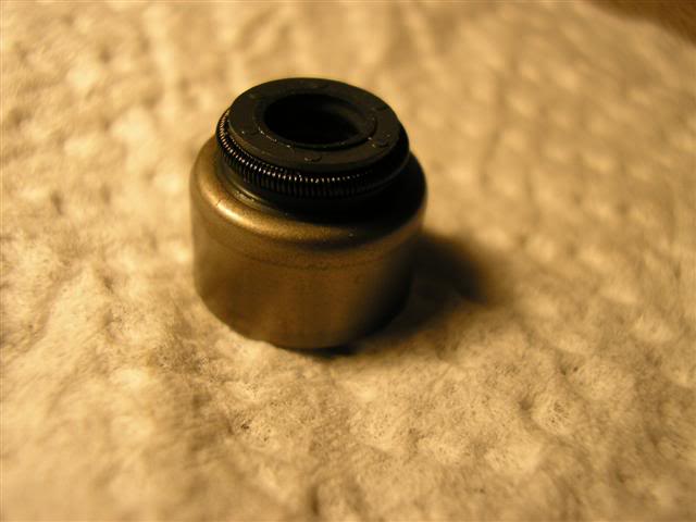
Exhaust Side
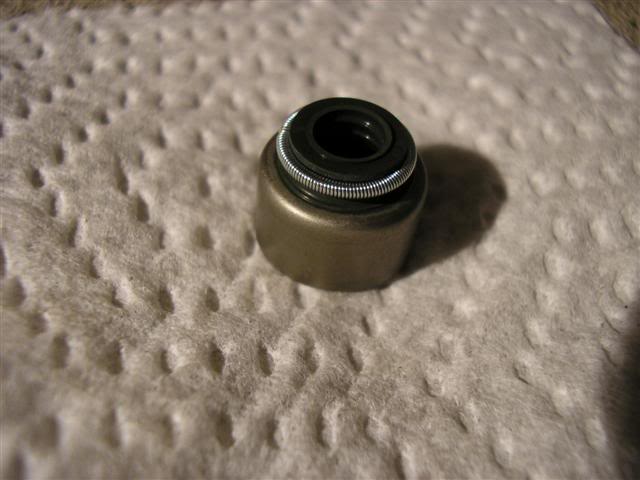
Intake Side
23) Grab your new valve stem seal and lube up the rubber part with oil or assembly lube and place it over your valve stem. I’m working on the intake side so I grab a white spring valve stem seal.
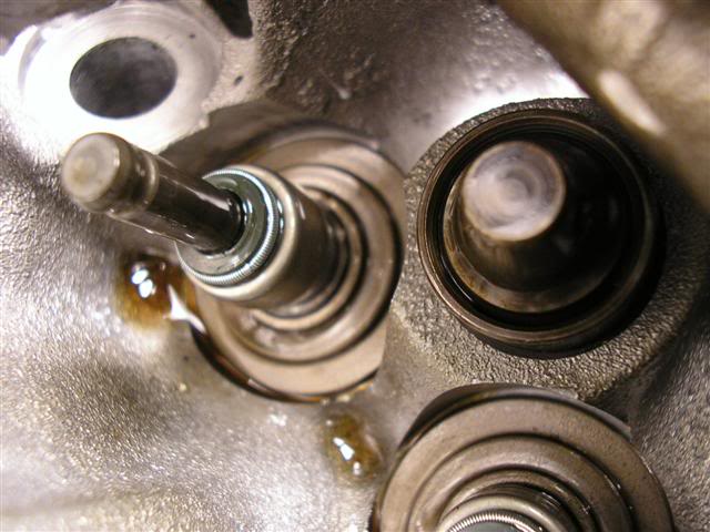
24) Placed over the valve stem and gently hand push it on, just to make sure it's seated straight and not crooked. THIS IS NOT correctly on the valve guide, it needs to be pushed on more. Look to next step.
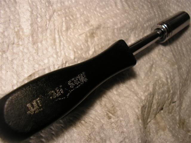
25) Take your 12mm deep socket with handle and place it over the valve stem seal. Then push it onto the valve guide. You’ll hear it click and feel the little click when it’s in place. There’s no need to hammer it on and is unnecessary
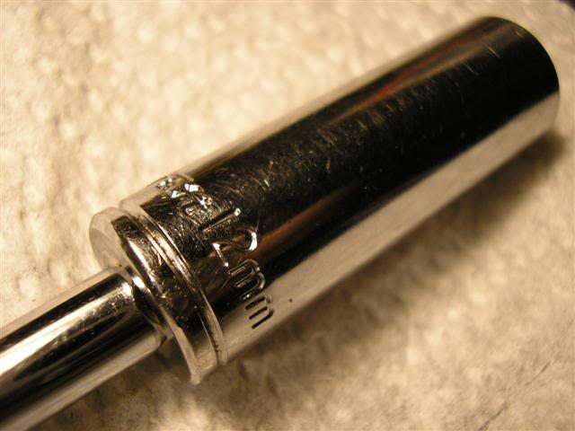
Just to show that 12mm fits the valve stem seal perfectly, without damaging the rubber or spring.
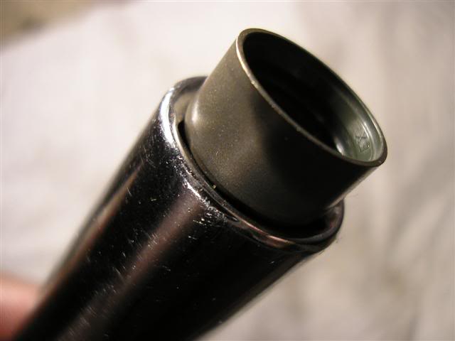
Properly installed on the valve guide

26) Grab your valve spring and place the inner spring inside the outer spring (if applicable) paying attention to which end has the tighter coils, because that is considered the bottom and goes towards the valve seat.
27) Lube up the valve springs in oil or assembly lube
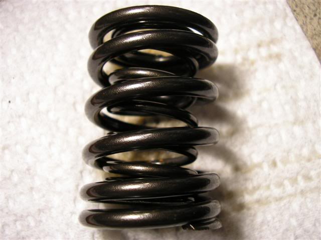
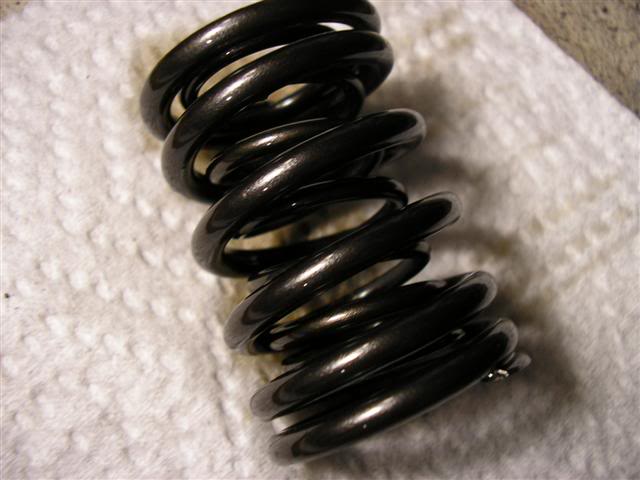
28) Place your valve spring(s) back into the head on the valve seat. The bottom of the spring has the coils closer together than the top
29) Place the retainer back on top of the valve spring(s)
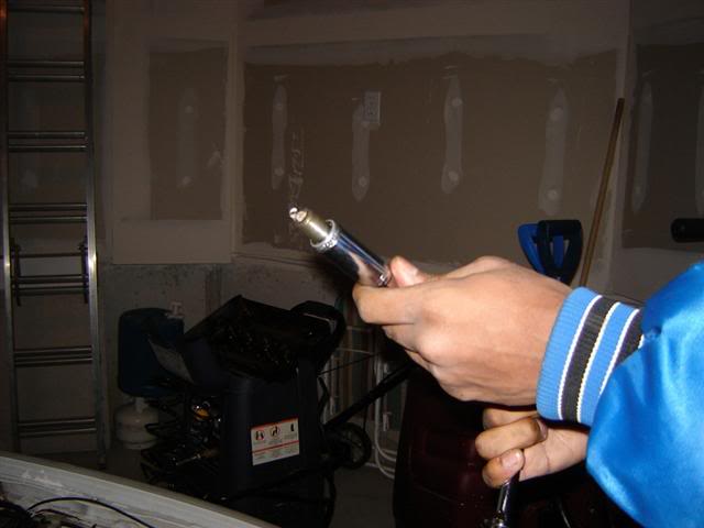
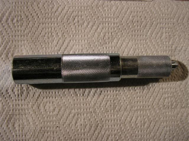
The process to get the valve keepers to hold the valve stem and stay put is different depending on which type of valve spring compressor you use. I’m using this type of valve spring compressor so this is the way to put the valve keepers back in.
The valve spring compressor I’m using looks like
30) Carefully place your valve keeper into the retainer. This process is made easier if the valve keeper is lube up with oil or assembly lube.
31) Place the valve spring compressor over the retainer and valve keeper combo
32) Now for the hardest part, trying your best to keep the valve spring compressor straight; begin to push down with all your might until your hands, shoulders, arms and whole body start to shake. That’s about the amount of pressure you need to put into compressing the spring enough to get the valve keepers to seat properly.
Now if this happens just remove the valve keeper and try again
Repeat steps 16 – 32 for the rest of the valve springs and valve stem seals. After your done give everything a once over to make sure it all looks right. Then grab your 12mm deep socket and rubber mallet and place the 12mm socket over the retainer and give the retainer a very light hit just to make sure that the valve keepers are in place and secure. Once you’re done move onto step 33.
All done
33) Make sure there’s still oil in the camshaft journals, if not add some. Engine assemble lube is fine as well
34) Place your camshafts back into its respective spots, intake cam on the intake side and exhaust cam on the exhaust side. Placing the spot where the key goes at the top.
35) Place the key into its spot on the camshaft and slide on the cam gear. Hand tighten the cam gear bolt for now.
B18A/B
B18C1/5
36) Place a generous amount of oil or assembly lube all over the cams
37) Re-install the cam holders onto the camshafts
B18A/B

B18C1/5

38) Then the cam holder plates back into its respective side and tighten the bolts down starting from the middle 12mm bolts working your way out and then finally the 10mm bolts.
39) Now grab two 5mm punches or allen keys and stick them through the cam plate holder and cam holder into the cam
Located here on a B18C1/5 head

I’m not too sure if it’s in the same place on the B18A/B heads, but you’ll be able to find it if you look around for it.
40) Torque down the cam gear bolts to 41 ft lbs for vtec heads and 27 ft lbs for non-vtec heads
B18A/B
B18C1/5
Exhaust Side
Intake Side
23) Grab your new valve stem seal and lube up the rubber part with oil or assembly lube and place it over your valve stem. I’m working on the intake side so I grab a white spring valve stem seal.
24) Placed over the valve stem and gently hand push it on, just to make sure it's seated straight and not crooked. THIS IS NOT correctly on the valve guide, it needs to be pushed on more. Look to next step.
25) Take your 12mm deep socket with handle and place it over the valve stem seal. Then push it onto the valve guide. You’ll hear it click and feel the little click when it’s in place. There’s no need to hammer it on and is unnecessary
Just to show that 12mm fits the valve stem seal perfectly, without damaging the rubber or spring.
Properly installed on the valve guide
26) Grab your valve spring and place the inner spring inside the outer spring (if applicable) paying attention to which end has the tighter coils, because that is considered the bottom and goes towards the valve seat.
27) Lube up the valve springs in oil or assembly lube
28) Place your valve spring(s) back into the head on the valve seat. The bottom of the spring has the coils closer together than the top
29) Place the retainer back on top of the valve spring(s)
The process to get the valve keepers to hold the valve stem and stay put is different depending on which type of valve spring compressor you use. I’m using this type of valve spring compressor so this is the way to put the valve keepers back in.
The valve spring compressor I’m using looks like
30) Carefully place your valve keeper into the retainer. This process is made easier if the valve keeper is lube up with oil or assembly lube.
31) Place the valve spring compressor over the retainer and valve keeper combo
32) Now for the hardest part, trying your best to keep the valve spring compressor straight; begin to push down with all your might until your hands, shoulders, arms and whole body start to shake. That’s about the amount of pressure you need to put into compressing the spring enough to get the valve keepers to seat properly.
Now if this happens just remove the valve keeper and try again
Repeat steps 16 – 32 for the rest of the valve springs and valve stem seals. After your done give everything a once over to make sure it all looks right. Then grab your 12mm deep socket and rubber mallet and place the 12mm socket over the retainer and give the retainer a very light hit just to make sure that the valve keepers are in place and secure. Once you’re done move onto step 33.
All done
33) Make sure there’s still oil in the camshaft journals, if not add some. Engine assemble lube is fine as well
34) Place your camshafts back into its respective spots, intake cam on the intake side and exhaust cam on the exhaust side. Placing the spot where the key goes at the top.
35) Place the key into its spot on the camshaft and slide on the cam gear. Hand tighten the cam gear bolt for now.
B18A/B
B18C1/5
36) Place a generous amount of oil or assembly lube all over the cams
37) Re-install the cam holders onto the camshafts
B18A/B
B18C1/5
38) Then the cam holder plates back into its respective side and tighten the bolts down starting from the middle 12mm bolts working your way out and then finally the 10mm bolts.
39) Now grab two 5mm punches or allen keys and stick them through the cam plate holder and cam holder into the cam
Located here on a B18C1/5 head
I’m not too sure if it’s in the same place on the B18A/B heads, but you’ll be able to find it if you look around for it.
40) Torque down the cam gear bolts to 41 ft lbs for vtec heads and 27 ft lbs for non-vtec heads
B18A/B
B18C1/5
Last edited by WildoutWhiteGSR; Apr 24, 2006 at 01:32 AM.
Thread Starter
Time to become a Premier Member!
Joined: Aug 2003
Posts: 4,816
From: Whitby
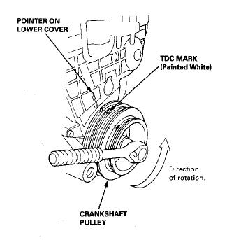
41) Now double check to make sure that the crankshaft is still at TDC by aligning the crank pulley with the arrow on the lower timing belt cover

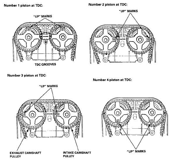
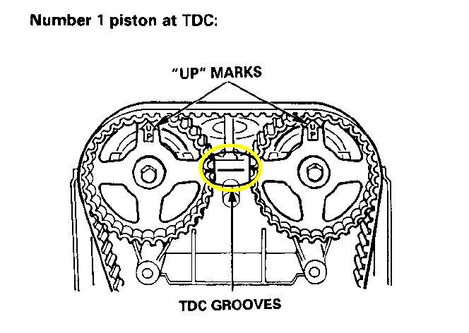
42) Once the crankshaft is aligned, double check to make sure that the cam gears are still aligned. Should look like this
43) Once it is, slide the timing belt back on making sure not to spin the crankshaft.
44) Rotate the crankshaft counter-clockwise ever so slightly to take the slack out of the timing belt. You do this via the crank pulley.
45) Tighten the timing belt tensioner bolt with your 14mm socket and rotate the engine via the crankshaft counter-clockwise a full rotation until your back at TDC for cylinder 1 and double check that nothing has moved and is still at TDC. Both at the cam gears and at the crank pulley. If the crank pulley or cam gears are off, loosen the timing belt tensioner bolt and try again. Once your done put back the plug into the timing belt cover.

46) Install the spark plugs back into the cylinders and if they need replacing, now is a good time to do so.
47) Double check that your valve lash is still within spec. If not adjust it to the specs your cam manufacture recommends. Stock specs can be found in the Helms or with a simple search, then install the valve cover back on.
48) Install the spark plug wires, and spark plug wire cover (if applicable) and the 15amp fuse if you took it out as well as the fuse cover.
49) Now that everything back together, look over your work area ensuring that everything is in the car and that you didn’t miss anything.
50) Start her up and listen for any abnormal sounds. If anything sounds wrong shut the car off immediatly.
Congrats you’re all done, shut her off or go for a drive.
Good Luck
42) Once the crankshaft is aligned, double check to make sure that the cam gears are still aligned. Should look like this
43) Once it is, slide the timing belt back on making sure not to spin the crankshaft.
44) Rotate the crankshaft counter-clockwise ever so slightly to take the slack out of the timing belt. You do this via the crank pulley.
45) Tighten the timing belt tensioner bolt with your 14mm socket and rotate the engine via the crankshaft counter-clockwise a full rotation until your back at TDC for cylinder 1 and double check that nothing has moved and is still at TDC. Both at the cam gears and at the crank pulley. If the crank pulley or cam gears are off, loosen the timing belt tensioner bolt and try again. Once your done put back the plug into the timing belt cover.
46) Install the spark plugs back into the cylinders and if they need replacing, now is a good time to do so.
47) Double check that your valve lash is still within spec. If not adjust it to the specs your cam manufacture recommends. Stock specs can be found in the Helms or with a simple search, then install the valve cover back on.
48) Install the spark plug wires, and spark plug wire cover (if applicable) and the 15amp fuse if you took it out as well as the fuse cover.
49) Now that everything back together, look over your work area ensuring that everything is in the car and that you didn’t miss anything.
50) Start her up and listen for any abnormal sounds. If anything sounds wrong shut the car off immediatly.
Congrats you’re all done, shut her off or go for a drive.
Good Luck
Last edited by WildoutWhiteGSR; Apr 24, 2006 at 01:37 AM.

Thread Starter
Time to become a Premier Member!
Joined: Aug 2003
Posts: 4,816
From: Whitby
Originally Posted by MaFiAbOy
Very good Trenell...U really know what your doing man
Hey maybe we can work on my build together
Hey maybe we can work on my build together
Warning though it's nuff pics
 :omg:
:omg:
Thread
Thread Starter
Forum
Replies
Last Post
beasty18c5
Integra Parts For Sale
0
Dec 21, 2009 07:59 PM
sashakthx
Integra Parts For Sale
1
Dec 9, 2009 09:05 PM
NixTEG
Integra Parts For Sale
0
Apr 21, 2007 05:57 PM